Test item 测试名称:Castors and Wheels - Castors for Furniture – Requirements 脚轮和轮子.家具用脚轮
Test info 测试内容:
|
Clause |
Test Requirement |
Castor Type |
Test Method (BS EN 12527: 1999) |
|
|
5.2 |
Impact performance |
All |
Clause 4.12 |
|
|
5.3 |
Electrical resistance |
C |
Clause 4.4 |
|
|
5.4 |
Manual lock Device |
Caster with manual lock device |
Clause 4.6 |
|
|
5.5 |
Dynamic (H:500 cycles; W:1000 cycles;S: 1000cylces) |
All |
Clause 4.13 |
|
|
5.6 |
Rolling resistance |
All |
Clause 4.15 |
|
|
5.7 |
Swivel test |
All |
Clause 4.16 |
|
|
5.8 |
Static load (24 hours) |
All |
Clause 4.9 |
|
|
5.9 |
Stem retention |
All |
Clause 4.17 |
|
|
Remark: |
||||
|
1. H type castor is hard tread and used on carpeted floor; W type castor is soft tread and used on tiled floor. C type castor is electrically condactive; S type is inclined axle castor. |
||||
|
2. Turnaround time 测试周期: 13 working days |
||||
|
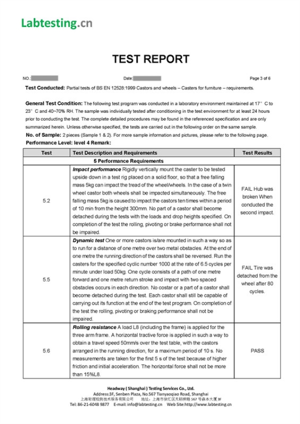
3. Sample required 送样规格: 7 pieces |
||||
|
5.2
|
Impact performance
|
||||
|
|
|
||||
|
5.3
|
Electrical resistance test
|
||||
|
|
The electrical resistance between the metal plate and the castor shall be tested when the casters are loaded with 5% to 10% of the nominal load ( a piece of wet blotting paper of the size of the contact area can be added if furniture castors or swivel chair castors are tested) . The resistance R shall be:
Conductive caster/ wheel: R ≦ 104Ω
Antistatic caster / wheel: 105Ω≦ R ≦107Ω
|
||||
|
5.4
|
Efficiency check of wheel braking and/or locking device
|
||||
|
|
The castor is placed on a horizontal smooth steel surface, clean from visible dirt. The braking and/or locking device is engaged. Apply to the mounting plane of the castor a load L1. Then gradually apply a horizontal tractive force (K1) in line with the running direction of the wheel. The force K1 shall be applied for 10 s then released. Gradually apply the force K1 once more for 10 s and monitor if the wheel revolves around its axle. Repeat the above procedure applying the force in the opposite direction. If during the application of the force K1 the wheel skids on the floor, change the surface material to a higher grip and repeat the test.
|
||||
|
5.5
|
Dynamic test for castors for furniture and swivel chairs only
|
||||
|
|
One or more castors is/are mounted in such a way so as to run for a distance of one metre over two metal obstacles. At the end of one metre the running direction of the castors shall be reversed. Run the casters for the specified cyclic number r2 at the rate of 6.5 cycles per minute under load L7. One cycle consists of a path of one metre forward and one metre return stroke and impact with two spaced obstacles occurs in each direction. (obstacle 2mm in thickness)
No costar or a part of a castor shall become detached during the test. Each castor shall still be capable of carrying out its function at the end of the test program. On completion of the test the rolling, pivoting or braking performance shall not be impaired.
|
||||
|
5.6
|
Rolling resistance test
|
||||
|
|
A load L8 (including the frame) is applied for the three arm frame. A horizontal tractive force is applied in such a way to obtain a travel speed 50mm/s over the test table, with the castors arranged in the running direction, for a maximum period of 10 s. No measurements are taken for the first 5 s of the test because of higher friction and initial acceleration. The horizontal force shall not be more than 15%L8.
|
||||
|
5.7
|
Swivel resistance test
|
||||
|
|
One or more castors shall be mounted on a linear or circular test machine with the castor(s) positioned at 90︒ to the running direction. A load L9 is applied to the castor(s). A horizontal tractive force provided by a test machine with a speed of 50mm/s, for a period of 2 s will cause the castors to swivel. The highest force required to cause the swivelling is measured, and the swivel resistance w4 shall not be more than 20%L9.
|
||||
|
5.8
|
Static load performance
|
||||
|
|
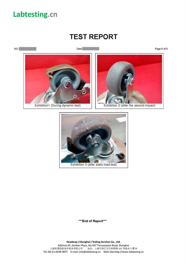
Apply the test load (either L1 multiplied by y1 or L6) for a period of time 24hours.
Readings must be taken after a time 24hours from when the load is removed and the wheel deformation shall not exceed 3% of the wheel diameter. On completion of the test the rolling, pivoting or braking performance shall not be impaired.
|
||||
|
5.9
|
Stem retention test
|
||||
|
|
A steadily increasing load is applied between the caster and the stem of the caster in the direction of the longitudinal axis of the stem until the required force L10 is reached. This force is then maintained for a minimum period of 2 min.
The force to remove the stem shall not be less than L10(Circular stem 15N; Other stem 30N)
|